RTS SAP612 User Manual
Browse online or download User Manual for Door intercom systems RTS SAP612. Model SAP612 Source Assign Panel User Manual [en]
- Page / 17
- Table of contents
- BOOKMARKS
Summary of Contents
Model SAP612Source Assign PanelUser Manual9350-6872-00 Rev E April 2007
Installation and Operation8System CapacityTo determine power supply loading, add together all of the user stations that will be powered from a particu
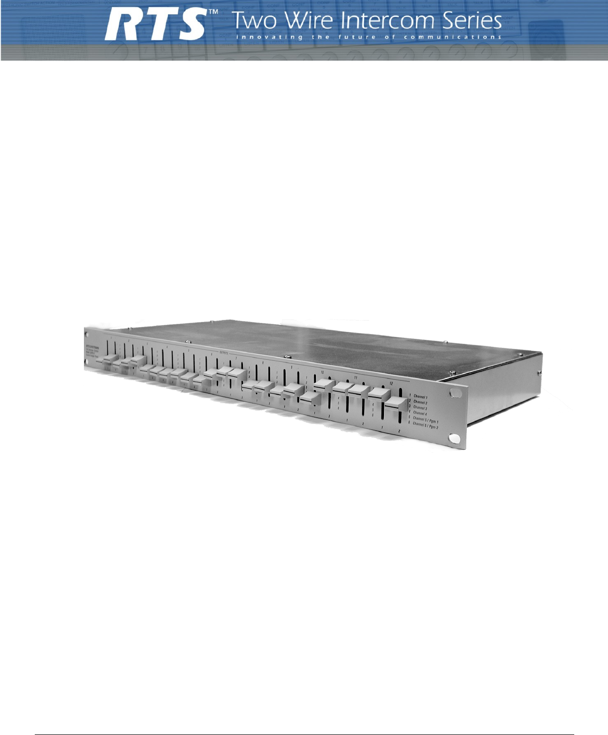
9OperationOperationThe front panel of the SAP612 contains 12 pairs of switches; one pair for each user station string. The user station strings 1-12 a
Installation and Operation10
11CHAPTER 3Diagrams and DrawingsAS6867 Assembly Drawing, Connector Board, Model SAP612AS6866 Assembly Drawing, Front Panel Switch BoardSD6872 Schemati
Diagrams and Drawings12
13FIGURE 4. AS6867 - Assembly Drawing, Connector Board
14FIGURE 5. AS6866 - Assembly Drawing, Front Panel Switch Board
15FIGURE 6. SD6872 - Schematic Diagram, Source Assign Panel Model SAP612
PROPRIETARY NOTICEThe product information and design disclosed herein were originated by and are the property of Telex Communications, Inc. Telex rese
TableofContentsDescription and Specification ...
3CHAPTER 1Description and SpecificationDescriptionThe Model SAP612 Source Assign Panel independently assigns each of 24 TW channels (12, two-channel T
Description and Specification4SpecificationsMaximum Switch Carrying Current1.0 ampere per outletMaximum Switch Breaking Current0.5 ampere per outletIn
5Reference ViewReference ViewFIGURE 2. SAP-612 Reference View
Description and Specification6
7CHAPTER 2Installation and OperationMechanical InstallationThe Model SAP612 mounts into a standard 19-inch rack and occupies one rack unit of height (
Related products and manuals for Door intercom systems RTS SAP612
 (28 pages)
(60 pages)
(28 pages)
(60 pages)
 (31 pages)
(11 pages)
(31 pages)
(11 pages)
© 2020, manymanuals.com. All rights reserved. | 0.520 s |
 Manymanuals.com
 Manymanuals.de
 Manymanuals.fr
 Manymanuals.it
 Manymanuals.pl
 Manymanuals.cz
 Manymanuals.es
 Manymanuals-pt.com
Comments to this Manuals